Electronics Check v1.2
This procedure is based on the Round 1 tests with some changes to accommodate the revised OMCv1.2 board
This stage is reached when the printed circuit boards (pcbs) have had all the components fitted to them. If the check reveals no fault, then it's safe to apply power.
Electrical tests
All modified, you can do the electrical tests. You will need a resistance meter for this. The ideal tool is a multimeter with a tone that indicates a closed circuit.
Open Motion Controller
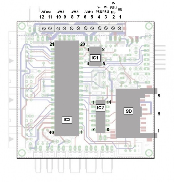
The tests are intended to check that connections exist where there should be connection, and that no connection exists where it should not. The tests are not exhaustive. Refer to the diagram below to identify pin numbers.
TODO: LATER DIAGRAM NEEDED:

Connect meter with Black probe to COM/V- and Red to V+
NB: there are test points on the OMC for 0V, 5V and 3.3V between the SD card socket and C18, arranged in a little square.
With black probe on 0v, put the red probe on IC1 pin 4, a beep is OK.
With black probe on 0v, put the red probe on IC2 pin 7, a beep is OK.
With black probe on 0v, put the red probe on IC3 pin 11, a beep is OK.
With black probe on 0v, put the red probe on IC3 pin 31, a beep is OK.
With black probe on 0v, put the red probe on SD pin 3, a beep is OK.
With black probe on 0v, put the red probe on SD pin 6, a beep is OK.
With black probe on 0v, put the red probe on screw terminals in turn 4,6,8,10
With black probe on terminal 5, put red probe in terminals 7,9,11 in turn, a beep is OK.
With black probe on 0v, put the red probe on screw terminals in turn, 1,3,5,7,9,11 a beep is NOT OK.
(An additional test that will work depending on the type of meter you use:
the Green LED may light with black probe on 0v and red probe on screw terminals in turn 5,7,9,11
the Red LED may light with red probe on 5V and black probe on terminal 1)
(The above test works for me if I put my meter in diode mode - Mark Davidson)
With black probe on 5v, put the red probe on IC1 pin 8, a beep is OK.
With black probe on 5v, put the red probe on IC3 pin 10, a beep is OK.
With black probe on 5v, put the red probe on IC3 pin 30, a beep is OK.
With black probe on 3.3v, put the red probe on IC2 pin 14, a beep is OK.
With black probe on 3.3v, put the red probe on SD pin 5, a beep is OK.
With black probe on 0v, put the red probe on IC3 pin 9, test for a beep while the reset button is pressed, and no beep when it is not pressed.
With black probe on 0v, put the red probe on 5v, NO beep is OK. (For those without a beeping meter, this should be somewhere in the 3-10 kΩ range).
With black probe on 0v, put the red probe on 3.3v, NO beep is OK. (For those without a beeping meter, this should be somewhere around 140 kΩ).
If everything is OK, plug in the three ICs taking care to see that each pin enters each contact correctly.
New ICs have their pins set a little wider than the socket, and it is helpful to bend them to be truly parallel. This can be done by placing the IC sideways with the pins on a flat surface and gently moving the IC body upright. Repeat for the pins on the other side.
The pcb is now safe to have power applied to it.
Dual Stepper Motor board
There is little to test on the DSM board:

Set your meter to measure in kΩ. With one probe on GND (the screw terminal nearest the corner of the board, or the contact surrounding one of the mounting holes in the corners), put the other probe on the upper (i.e. most easily accessible) pin of the black ribbon connector nearest the screw terminals. Hold the contacts in place until the value settles down — this may take up to 30 seconds. You should get a stable reading of around 73 kΩ (plus or minus 1).
Note that if you have added any jumpers to the board, the measured resistance will be lower.
