Print Head: Extruder Assembly
Idler Block Assembly
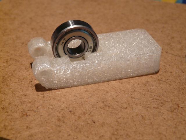
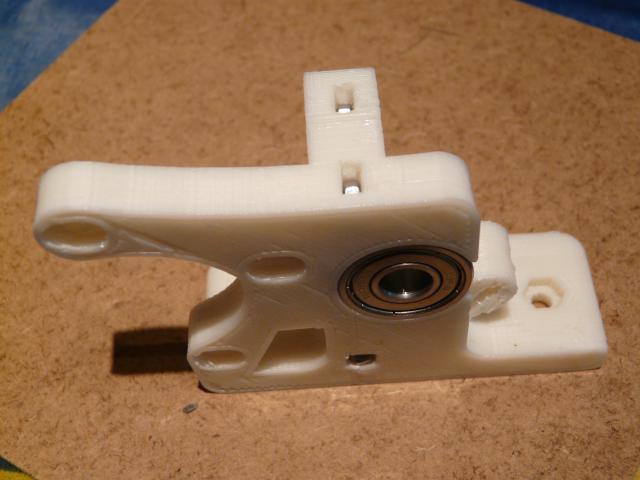
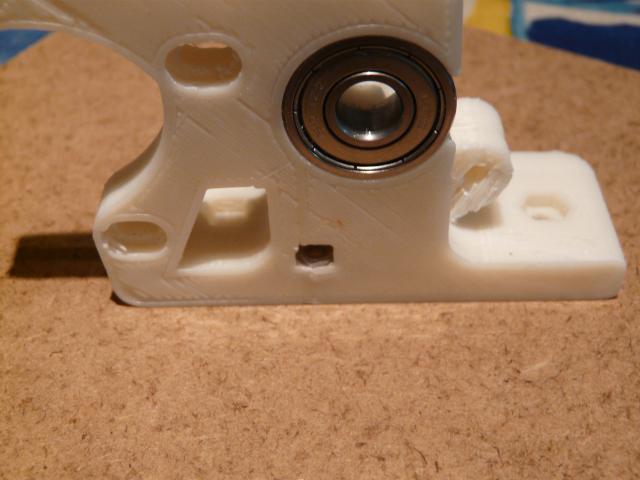
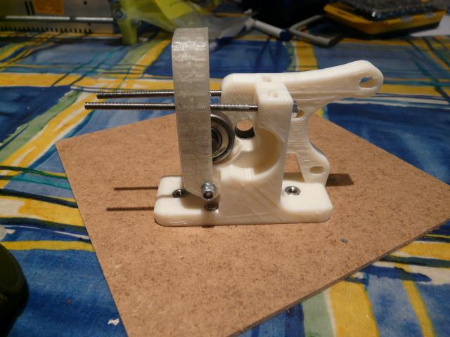
Insert a "608" bearing into the slot in the idler block.
Push it (hard - ideally in a vise or cramp) so that the outer race has been forced through the projecting lips that are intended to grip the inner race. DO NOT PSUH IT ALL THE WAY IN. You need to be able to push the 8mm smooth bar through the centre of the bearing.
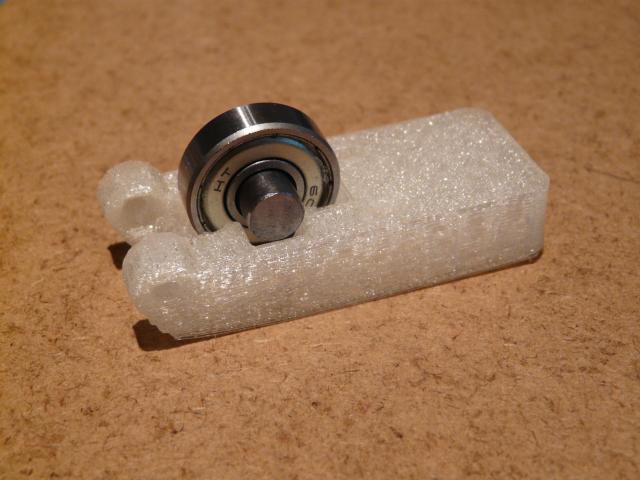
Insert the 18mm length of 8mm smooth bar through the centre of the bearing. Align the ends of the rod with the ends of the cut out provided to hold the bar in place.
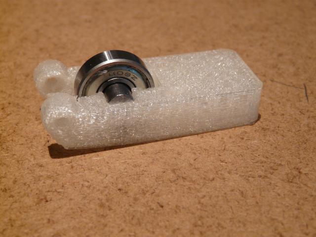
Push the bearing and rod assembly home. This might need a vise or other form of press. The movement should create two "clicks" along the way - so be sure that it is fully pushed in.
The outer race should protrude slightly (~1mm) from the back of the idler block. Note that in the pictiure above, the back of the idler does not sit flat.
Put the idler block assembly to one side.
Extruder Block Assembly
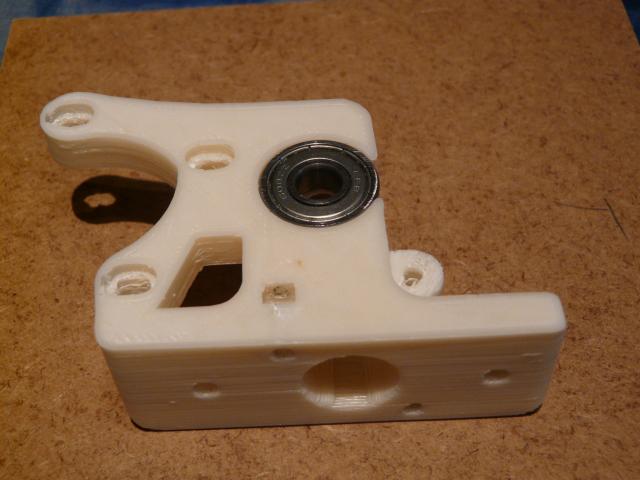
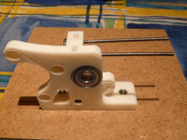
Insert a "608" bearing into the gear side of the extruder block. (The largest flat surface on the plastic part.) Again this might require a vise or cramp. The bearing should bed a tight fit but not require massive pressure. If necessary, ease the tightness of the fit using glass paper.
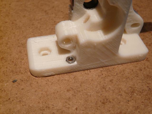
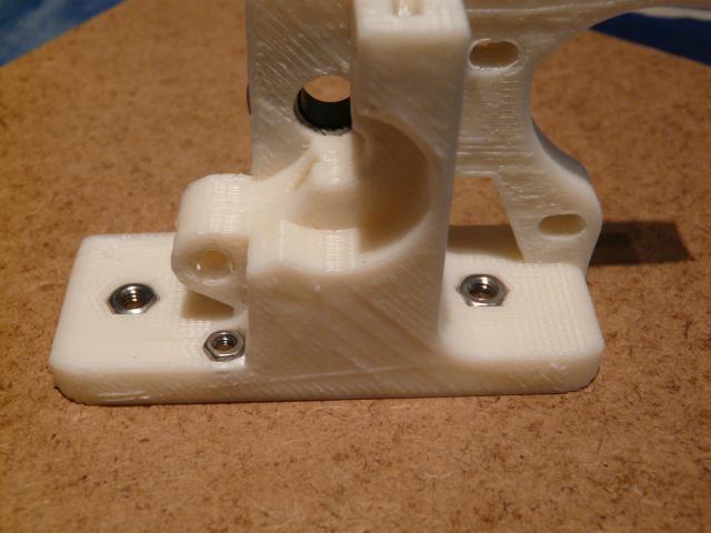
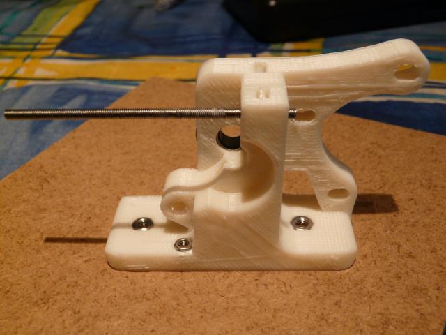
Insert 2 x M3 nuts in the slots for captured nuts on the top of the block. (These retain the threaded rods that carry the springs.) These should be a loose fit. They should fall out if the block is inverted. If the slots are too small ease then out using a square needle file.
Insert 2 x M3 nuts in the recesses for 3mm captured nuts in the base of the extruder block. (These retain the bolts that hold the hot end in place against the extruder block.)
Insert 2 x M4 nuts in the recesses for 4mm captured nuts in the base of the extruder block. (These retain the bolts that hold the extruder block to the x-carriage.)
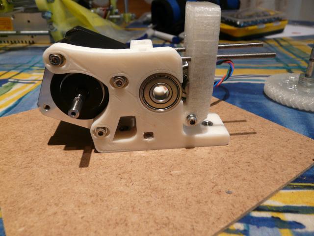
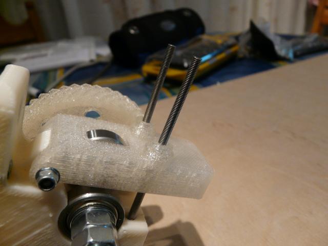
Insert one of the 75mm x M3 threaded rods into the hole parallel to and nearest the motor side of the extruder block and screw it through until there is enough rod to fit a M3 washer and nut.
Fit the nut & washer and tighten slightly to lock the rod in place.
Insert the other 75mm x M3 threaded rods into the hole parallel to and nearest the gear side of the extruder block and screw it through until the length matches the other 75mm x M3 rod.
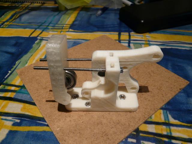
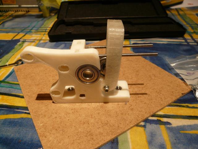
Pass both 75mm x M3 threaded rods through the two oval holes in the extruder block so that the idler block pivot matches the extruder block pivot and the protruding part of the bearing faces towards the main block of the extruder body.
Push the idler block pivot onto the extruder block pivot and pass an M3 x 30mm bolt through an M3 washer and then through the pivot holes in the idler block and extruder block.
Fix in place with a M3 washer and nylock nut.
Fit the motor to the extruder block using 3 x M3 x 10mm bolts.
Preparing the large gear
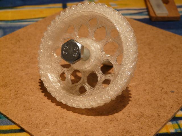
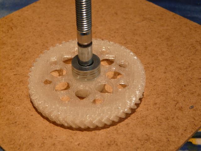
Push the hobbed bolt through the large herringbone gear. Do not engage the hexagonal head of the bolt with the hexagonal cut out in the centre of the large gear.
Place 5 x M8 washers on the hobbed bolt on the inside of the large herringbone gear.
Note that the hobbed bolt is (incorrectly) pushed all the way through in this picture - to allow the picture to be taken.
Preparing the small gear
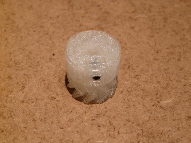
Place an M3 nut in the slot in the end of the small herringbone gear.
Insert an M3 grub screw into the hole in the side of the small herringbone so that it engages with the M3 nut but doesn't protrude into the 5mm hole running axially through the small herringbone gear.
Fitting the gears
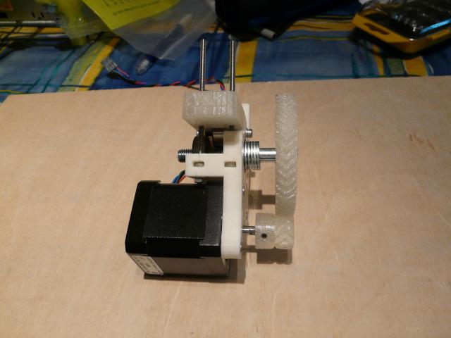
Place the small gear on the motor shaft of teh extruder so that the grub screw aligns with the flat on the motor shaft. Do not push it all the way onto the shaft at this time.
Place the partially assembled large gear onto the small gear so that the gears mesh. Manipulate the position of the large gear and hobbed bolt so that the hobbed bolt passes through the 608 bearing.
Push the hobbed bolt through the large gear until its head engages with the hexagonal cut out in the centre of the gear.
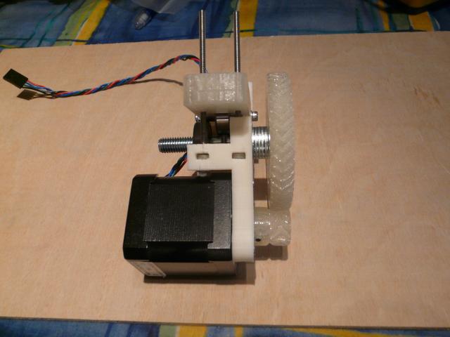
Then push the large gear and small gear so that they move towards the extruder body together (i.e. stay meshed) until the large gear is spaced from the 608 bearings by the 5 x M3 washers. Fit the third 608 bearing into the motor side of the extruder body, passing it over the threaded portion of the hobbed bolt.
Fix the small gear in place on the motor shaft, using the grub screw.
Make sure that the groove in the hobbed bolt is aligned with the hole down the centre of the extruder body.
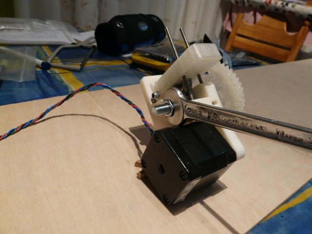
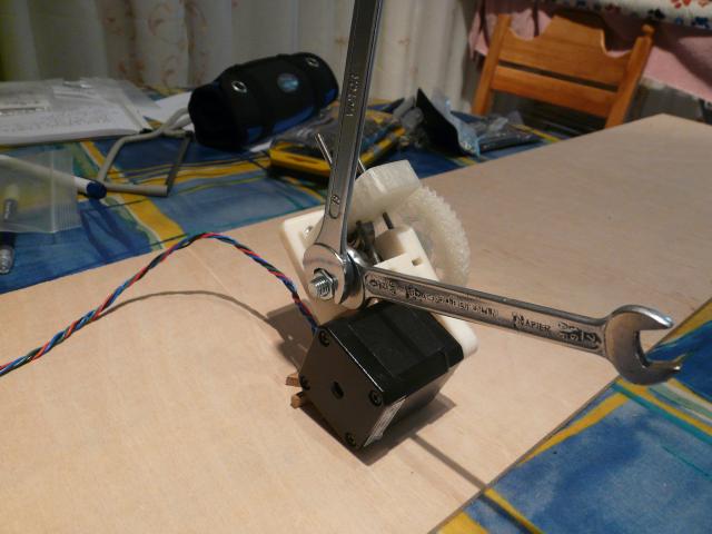
If the hobbed bolt is aligned, place one M8 washer over the threaded end of the hobbed bolt and use your fingers to tighten an M8 nut onto the hobbed bolt. Once it is "finger" tight, slacken it by half a turn and hold it in place with a spanner.
Place a second M8 nut on the threaded end of the hobbed bolt and use your fingers to tighten it to the first M8 nut. Lock the two nuts together with spanners
Fixing the springs
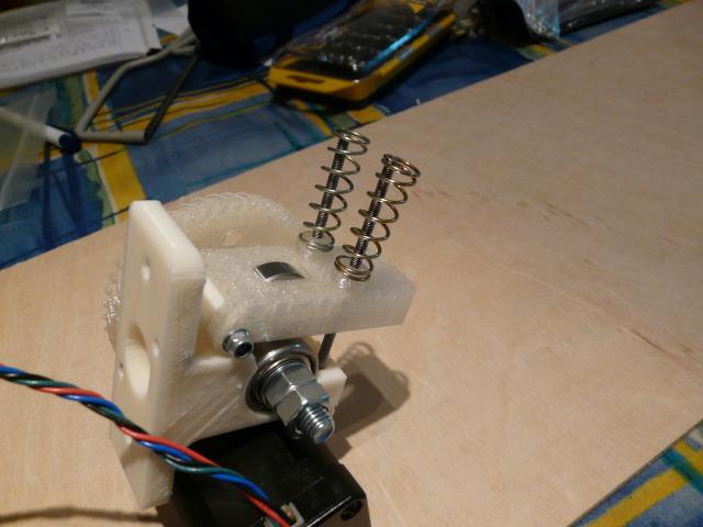
Place 1 x plastic screw seat onto each 75mm x M3 rod, with the larger diameter towards the back of the idler block.
Place 1 x spring over each 75mm x M3 rod so that it locates over the smaller diameter end of the screw seat.
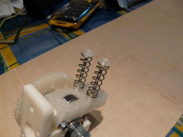
Place 1 x plastic screw seat onto each 75mm x M3 rod so that the smaller diameter end of the screw seat engages with the spring.
Compress one spring with one hand and place an M3 washer over the protruding 75mm x M3 rod. Keeping the spring compressed, place an M3 nut on the protruding 75mm x M3 rod.
Repeat for the other spring.
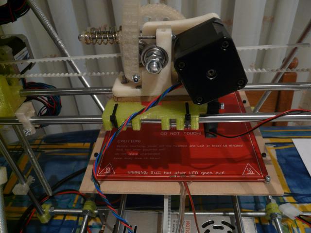
Mounting the Extruder on the X-carriage
Before mounting the extruder on the X-carriage, insert two M3 nuts into the nut traps on the X-carrage - these will be used to attach the fan (seen on the right of the x-carriage in the picture). Otherwise it can be quite tricky to get them in with the motor over them.
Place the piece of laser cut plywood onto the bottom of the extruder body so that the 3mm and 4mm holes in the plywood align with the corresponding holes on the extruder body.
Then place the assembled extruder/plywood on the x-carriage so that the M4 captured nuts in the extruder body align with the central holes on the x-carriage. Fix the extruder in place using 2 x M4 x 16mm set screws. The extruder springs should point towards the x-axis motor.

