Print Head: Hot End Assembly
About the Hot End
The hot end that you will be building is a J Head Mk III-B from Brian Reifsnyder.
The parts
J Head hot end:
Nozzle
PTFE liner
Heating Resistor
100KΩ Thermistor
PEEK thermal barrier/extruder body
Mounting washer
PTFE tubes
See Heatshrink & PTFE Reference for details.
Small PTFE tube
Transparent tube. Insulates the thermistor leads. Should be pre-fitted to the thermistor leads.
Large PTFE tube
Transparent tube. Insulates the resistor leads. Needs to be cut into 25mm lengths.
Heatshrinks:
See Heatshrink & PTFE Reference for details.
Small high temp heatshrink
2mm diameter, transparent. Insulates thermistor/cable joint. Needs to be cut into 40mm lengths.
Large high temp heatshrink
4.8mm diameter, transparent. Insulates resistor/high temperature cable joint. Needs to be cut into 40mm lengths.
Large "normal" heatshrink
4.5mm diameter, black. Insulates high temperature resistor/resistor extension cable joint. Needs to be cut into 40mm lengths.
Bootlace ferrules:
Small bootlace ferrule
Large bootlace ferrule
Cables:
See Wires Reference for details.
Extruder thermistor cable
Single twisted pair.
High temperature extruder resistor cable
Extruder resistor extension cable
White lamp cable.
Assembly
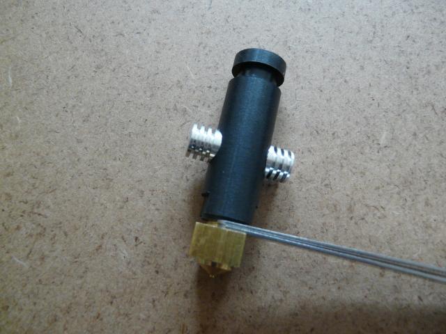
Step 1 Measure the gap between the top of the brass extruder and the bottom of the black PEEK extruder body. We used a feeler gauge. This is to prevent over- or under- tightening when reassembling the hot end.
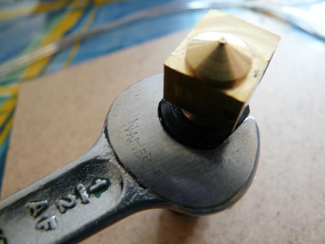
Step 2 Put a 13mm (or 1/2"AF) spanner on the flats at the bottom of the black PEEK extruder body.
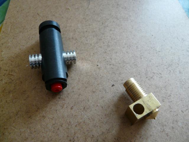
Use another 13mm (or 1/2"AF) spanner on the longer sides of the brass extruder body and undo the brass extruder body from the black PEEK extruder body.
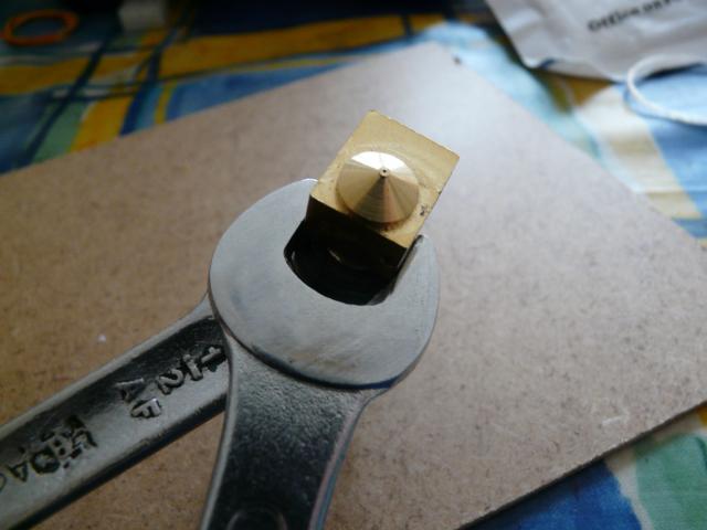
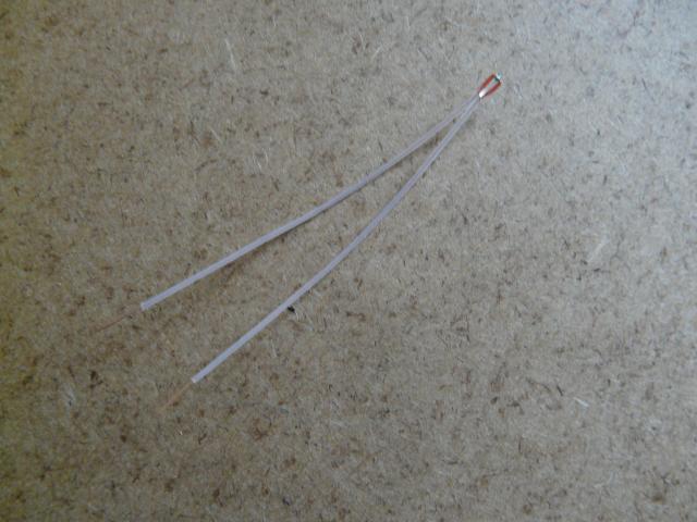
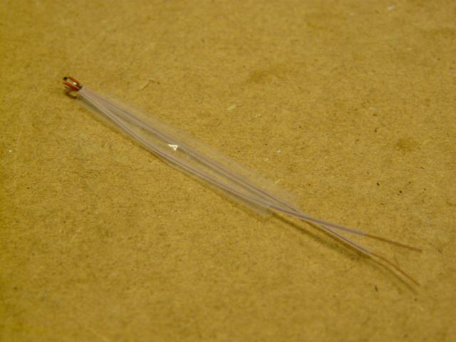
Step 3 Check that the thermistor has PTFE tube on both leads.
Place a 36-40mm length of small high temperature heat shrink over the PTFE tube on each thermistor lead. (See Heatshrink Reference for details.)
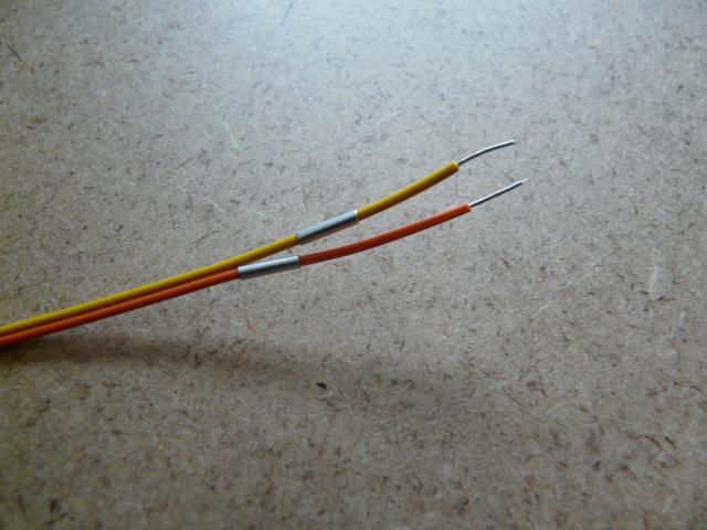
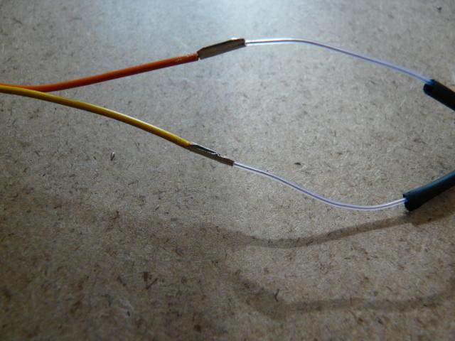
Step 4 Strip back both leads of the extruder thermistor cable to the same length as the small bootlace ferrules. Place a small ferrule over each lead. (Note that the wiring is likely to be white/coloured twisted pair, not the red/yellow cable shown in the photo. See Wires Reference for details.)
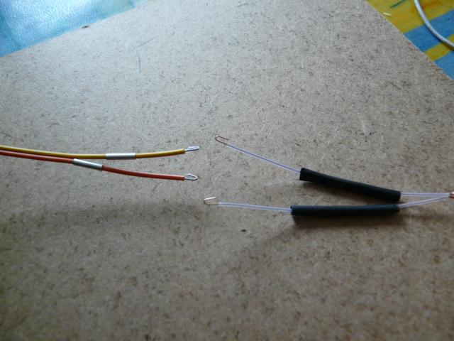
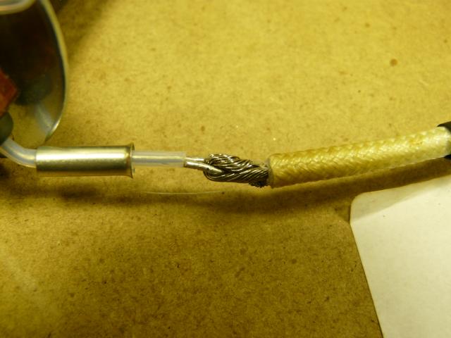
Step 5 Bend each of the un-insulated portions of the thermistor leads and extruder thermistor cable into hooks. (Note: The heatshrink should be transparent, not the black shown in this photo).
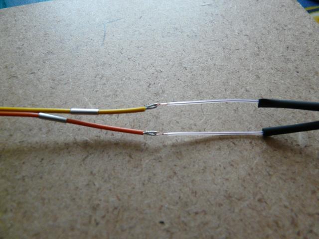
Hook one of the un-insulated portions of the thermistor leads into one of the un-insulated portions of the cable. Repeat with the other leads.
Step 6 Slide the bootlace ferrules over the un-insulated portions of wire. Crimp both bootlace ferrules.
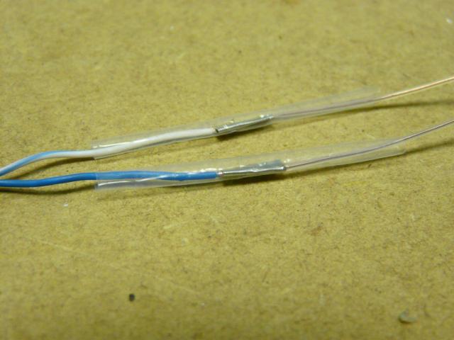
Step 7 Position the heatshrink from each thermistor lead over the bootlace ferrule.
Heat the heatshrink pieces to tighten them onto the bootlace ferrules. Suggested ways to do this, in order of preference, are: a small heat gun (gas soldering iron with the hot air bit on); a paint stripper hot air gun, or the broad part of the tip of a soldering iron.
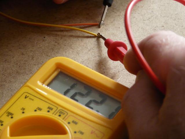
Check the continuity of the thermistor to ensure the bootlace ferrule connections are sound. A measurement of just under 100KΩ is expected (depending on room temperature).
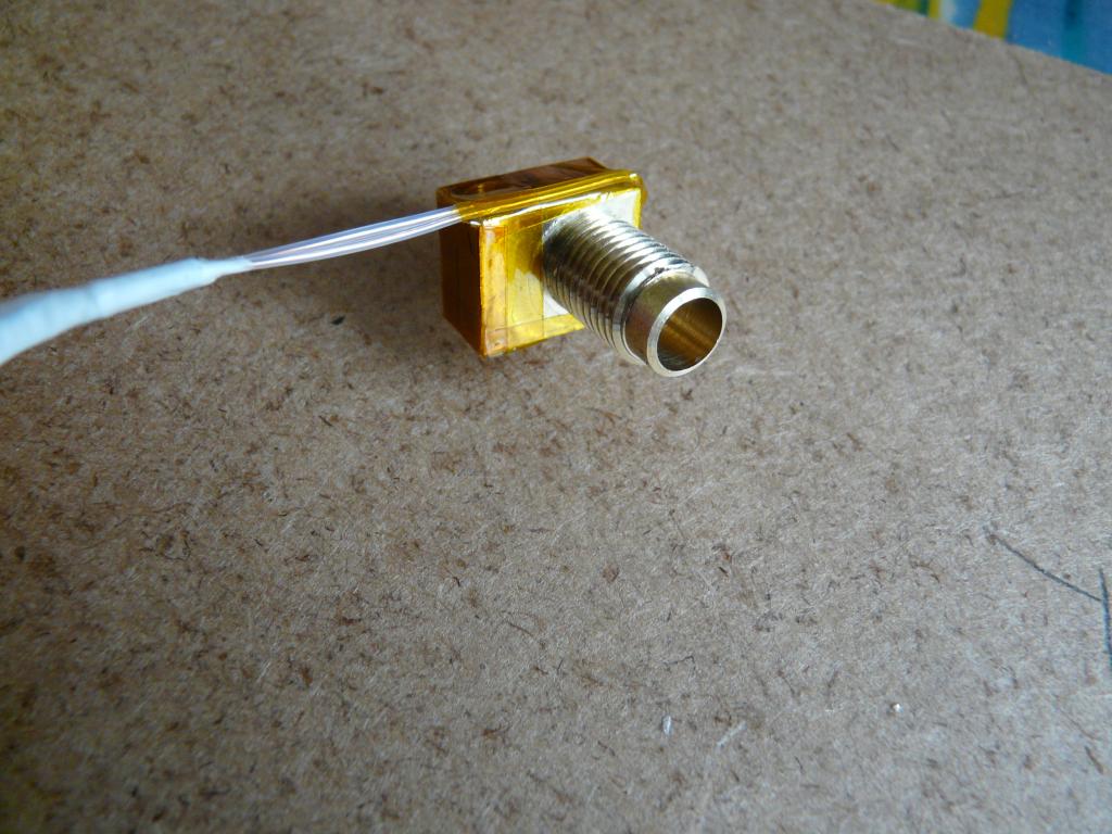
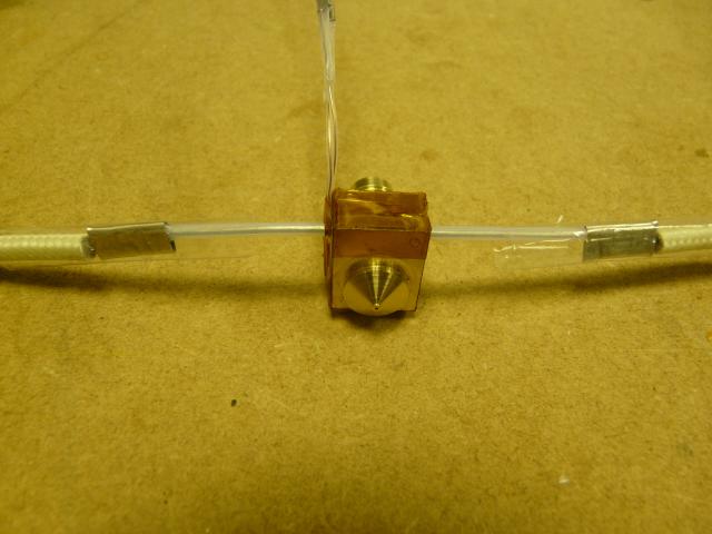
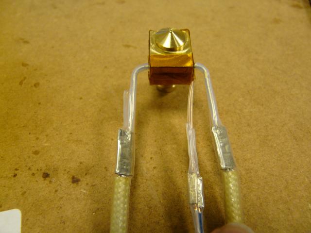
Step 8 Fit the head of the thermistor into the hole in the brass extruder body. Bend the thermistor leads around the body of the brass extruder as shown in the photos.
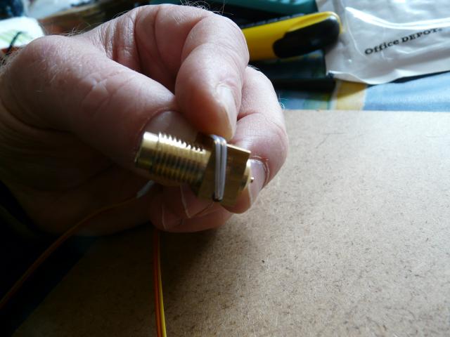
Step 8 Fix the thermistor leads in place using Kapton Tape.
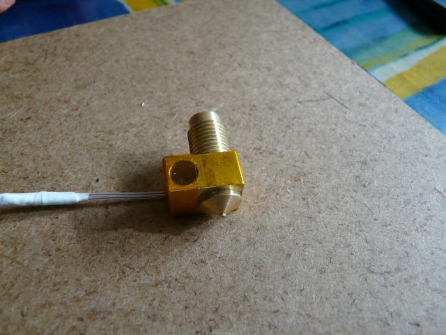
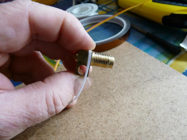
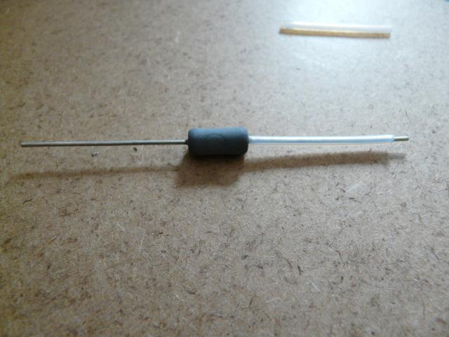
Step 9 Cut two 25mm lengths from the larger PTFE tube. Fit one of the lengths to one of the leads of the high power resistor.
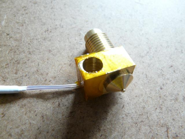
Step 10 Cut the Kapton Tape away from the hole in the brass extruder body on the opposite side to the thermistor leads.
Step 11 Pierce a hole in the Kapton Tape on the brass extruder body on the side that the thermistor leads run down. The hole needs to be in the centre of the hole that runs through the brass extruder body.
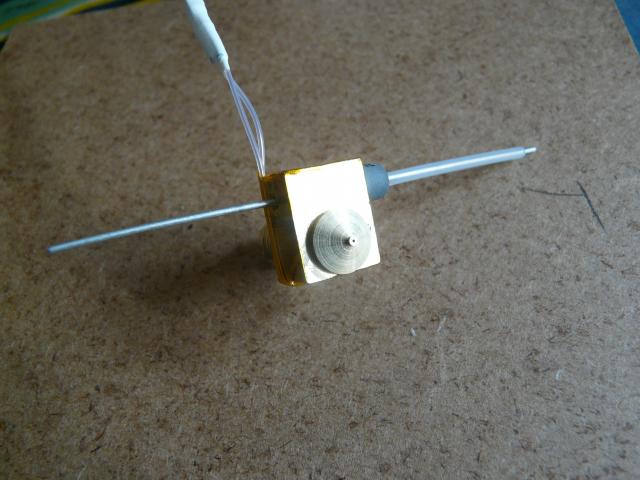
Step 12 Feed the power resistor through the hole in the brass extruder body. The lead without the PTFE tube should pass through the hole in the brass extruder body first and then through the hole pierced in the Kapton Tape.
Step 13 Once the resistor is in place, put the remaining piece of PTFE tube on the lead of the power resistor. Note: If the power resistor is not a snug fit in the brass extruder body, wrap it with a small piece of aluminium foil until it is and then fit the resistor into the brass extruder body.
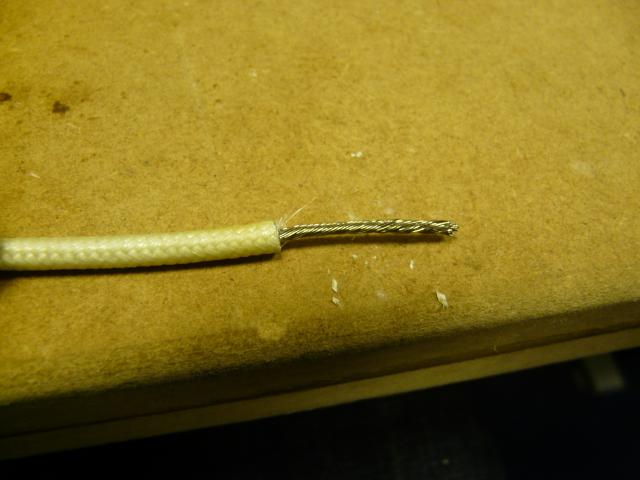
Strip back the high temperature leads for the power resistor to the same length as the large bootlace ferrules and twist the wire strands together.
Step 14 Fit a bootlace ferrule over one of the power resistor leads. As with the thermistor connection, create hooks from the ends of the wires and join together.
Step 15 Slide the ferrule over the connection and crimp. Cut two 40mm lengths of large high temperature heatshrink and place over the bootlace ferrule. Heat to shrink the tube into position.
Repeat for the other lead.
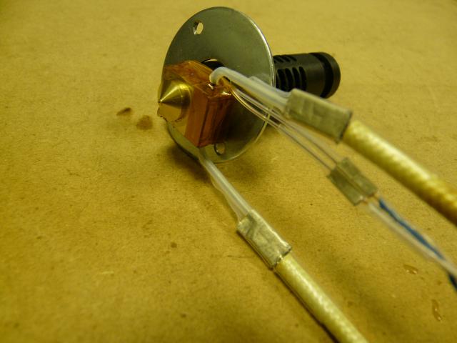
Step 16 Using a pair of pliers, bend the resistor wires through 90 degrees to run parallel with the thermistor leads.
Step 17 Place the washer over the threaded part of the brass extruder body. Screw the brass extruder body into the PEEK body. Tighten the brass extruder body into the PEEK body until the gap between the top of the brass extruder body and the bottom of the washer is the same as was measured at the start of this assembly.
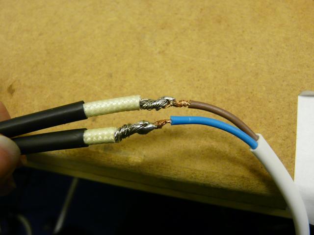
Step 18 Strip the ends of the high temperature resistor cable and lamp cable to about 20mm and twist the strands together. Put 40mm lengths of large "normal" heatshrink over each of the high temperature resistor cables. Again, form hooks from the ends of the leads and join together, twisting to secure the ends.
Step 19 Solder the join to ensure a good connection.
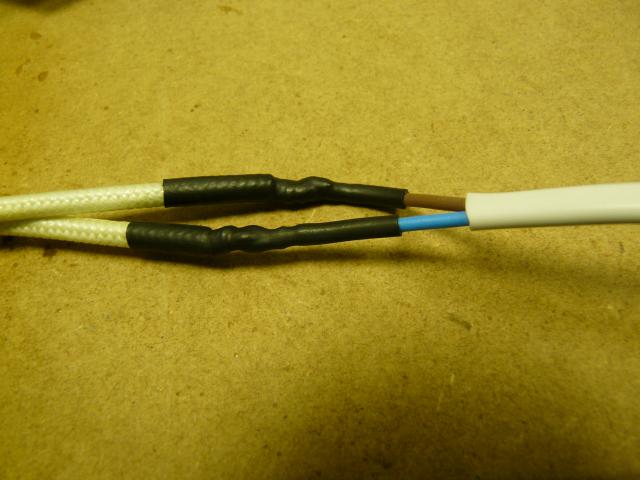
Step 20 Slide the heatshrink over the join and heat to shrink.
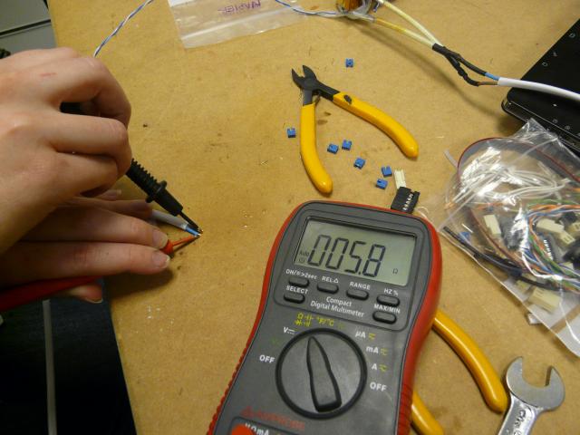
Step 21 Check the continuity of extruder resistor connections with a meter. A measurement of around 6Ω is expected.
Step 22 Fasten the thermistor lead to the power resistor leads using PTFE plumbers tape.
Attaching to Extruder Body
Tip: You may find it useful to place a hand mirror or similar on the heated bed.
When building the extruder body, there should have been two nuts added that were left loose and unused, you may well have added temporary bolts to prevent them from being lost - if so, remove them now.
Locate the 2 x M3x45 bolts, or better still M3x50 if you have them.
Attach the hot end into the extruder body with the two bolts, orientating the cylindrical heatsink in the middle so that it is well away from the plastic and not touching anything - parallel to the smooth rods would make sense. Whilst the bolts should be right - the large washer will bend if you over-tighten.

