Electronics v1.2 parts
Annotation is incomplete... will be finished when people respond to the 'TODO' items or fix them themselves. Some progress is being made on this, last edit 2012-10-28, but help is still needed.
If you want to check what's in your box (and we recommend you do check), get the list of materials from https://docs.google.com/spreadsheet/ccc?key=0AlKLZQD6xflKdFlQTXQ2V3NYaWkwVDFuNlhNYk4wMmc and use the photos below.
As with many pages on this site, you can click on the thumbnails to get a larger image, though for best results you need to enable Javascript in your browser.

Resistor 10k, 3 off
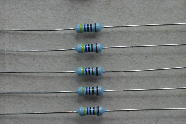
Resistor 4k7, 6 off

Resistor 100k, 3 off
Resistor 1k, 2 off
Resistor 220r, 1 off

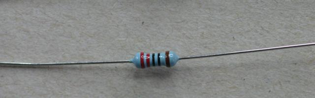
Resistor 470r, 7 off.
For round 3, this is replaced by 510r (green, brown, black, black - brown).


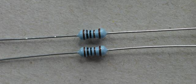
Resistor r22, 8 off
(TODO: note to self, rotate this pic)

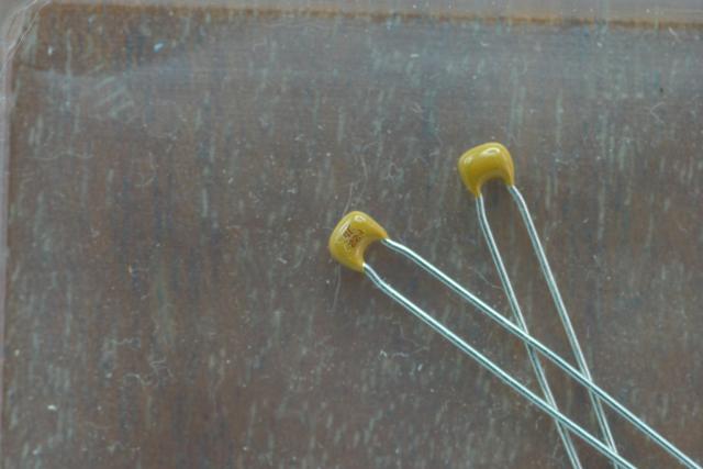
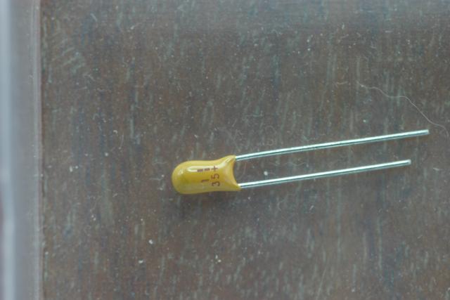
Capacitor Ceramic 100nf, 18 off. Some kits have 470nf capacitors, the value isn't critical, these capacitors are used to smooth the voltage supplied to nearby chips, reduce interference etc.
There is, believe it or not, a legend on each capacitor, to indicate its value. Using a contrasting colour for the printing would make life too easy, so someone at the manufacturer with a sense of humour chose light grey on the blue background. '104' indicates 100nf, '474' indicates 470nf (the final '4' means four zeroes).

Capacitor Ceramic 100pf, 4 off
Capacitor Ceramic 22pf, 2 off

Capacitor Tantalum 22uf, 3 off. These are easily confused with the 1uf capacitor, so pay attention to the labelling.
For Round 3, these appear to have been replaced by capacitors labelled 33, so presumably 33uF.

Capacitor Aluminium 10uf, 3 off

Capacitor Ceramic 10uf, 3 off. Did you spot that these capacitors have the same value as the previous one? Keep this in mind, because they're not interchangeable, so when you build your boards you'll need to distinguish between these two types.
There's very fine printing on these, examine them with a magnifying glass. You should see '106', in other words a value of '10' with 6 zeroes following (because there's a million pf in 1uf).
Capacitor Tantalum 1uf, 1 off. This is easily confused with the 22uf capacitors, so pay attention to the labelling.
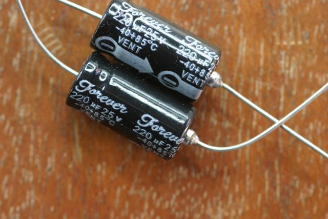
Capacitor Tantalum 220uf, 2 off

Inductor 250uh, 1 off. Note that this looks pretty much like a resistor, but it really isn't. If you measure its resistance you'll find it very low.

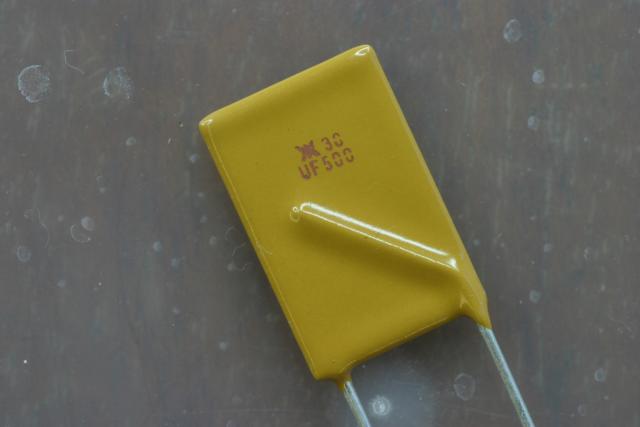
PTC Fuse 500mA, 1 off. Both sides are shown here. You may think it looks rather like a ceramic capacitor. When you can distinguish such components at a quick glance, you'll have reached Zen electronic enlightenment.


PTC Fuse 5A, 2 off.
As you can see, these 2 components are different. No, I don't know why the parts list shows 2 off, yet I've received two different fuses. But I've not reached Zen (see above).
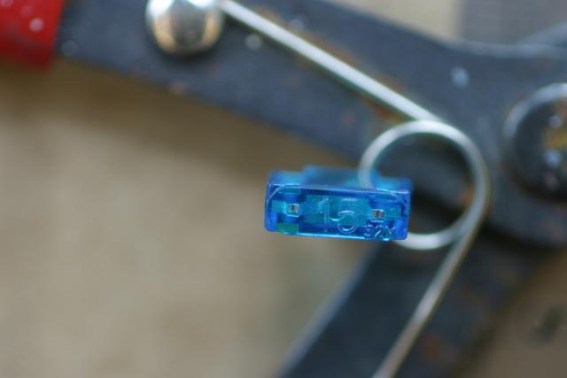
Blade fuse holder 15A, 1 off.
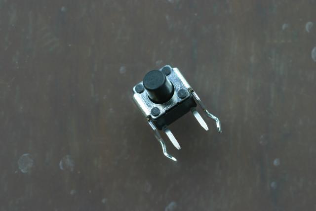
Tack switch, 1 off

Green LED 3mm, 1 off
Red clear LED 3mm, 1 off
Red dome LED 1.8mm, 2 off
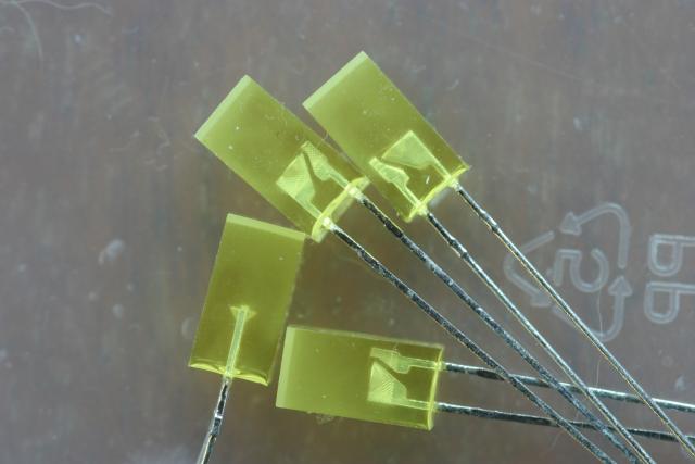
Yellow LED 5mm, 4 off
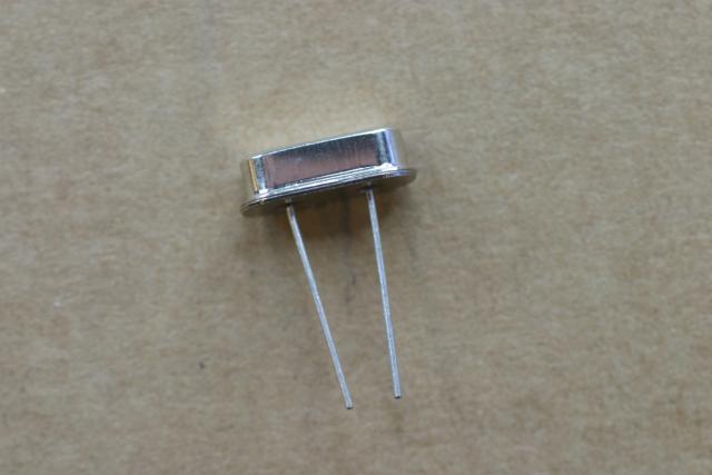
Crystal 20MHz, 1 off
You can't see this in the side view photo, but if you look at the top of the crystal you'll see '20.000' etched into the metal.

 N-Mosfet IPI80N03S4L, 1 off
This, and the other semiconductors listed below, are sensitive to the high voltages that static electricity can generate. Keep them in the special bag they're supplied in and earth yourself, e.g. by touching a metal pipe or PC case.

N-Mosfet STP55n, 2 off
Note these may be substituted with 2 more NTD4963N-1Gs for round 3 builds.

N-Mosfet NTD4963N-1G, 1 off

P-Mosfet IPP80P03P4L-04, 1 off

Comparator LM393, 1 off

Buffer 74AC125N, 1 off
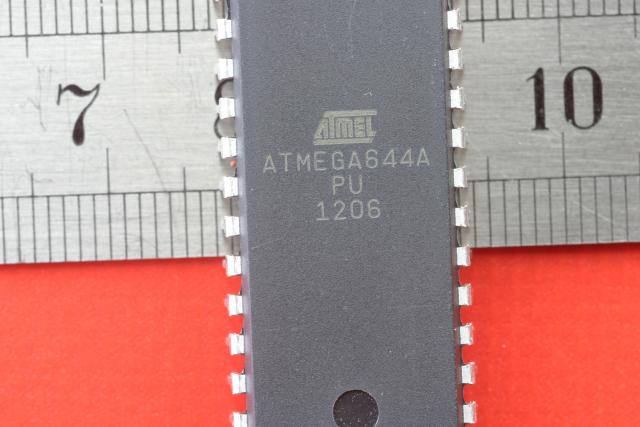
Microcontroller Atmega644P, 1 off
This one is easy to identify, it's the 40 pin chip, bigger than the rest.

Ldo regulator LP2950Z, 1 off

Voltage regulator 7805, 1 off

Stepper driver TB6560, 4 off
These are also easy to spot, bigger than the other chips except for the 40 pin microcontroller.

Rectifier diodes 1N4004, 3 off.
You may have slightly different ones, anything starting 1N400 is fit for purpose here.

Signal diode 1N4148, 1 off.
This is seriously tiny! As with several other such components, if you think it's missing, have a good look in the crevices of your box. If you were daft enough to tip all the components out onto the table to start with, have a good look on the floor, in the remains of your Chinese take-away, and in the cat litter tray. It's amazing how these things jump, they're the size of fleas and just as lively!
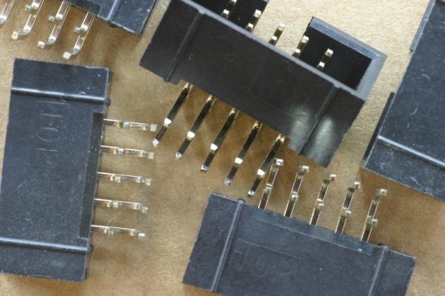
IDC headers, boxed, 5 off

2 way right-angle KK header, 4 off
KK? No, I don't know what it means. If you don't either, just lie back and enjoy the ride.
Looks like this should be 5 off, at least for Round 3. One each for the Dual Stepper Motor boards and three for the Controller board (TBC).

3 way right-angle KK header, 3 off
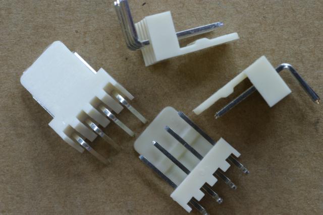
4 way right-angle KK header, 4 off
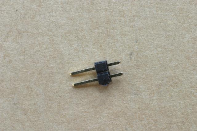
2 pin header, 2 off

2*2 pin header, 4 off

2*3 pin header, 1 off

2*4 pin header, 4 off

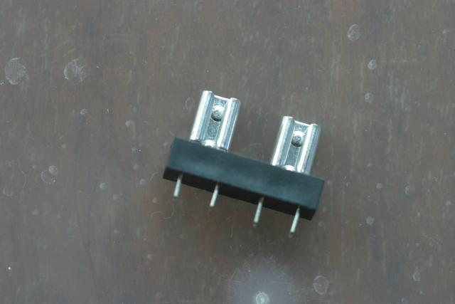
6 pin right-angle header, 1 off
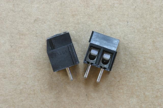
Screw terminal 2 way (black), 2 off

Screw terminal 6 way (blue), 2 off
Note that these are each a pair of 3-way blocks which clip together, and they may have come apart in the bag.

OMC printed circuit board, 1 off

DSM printed circuit board, 2 off
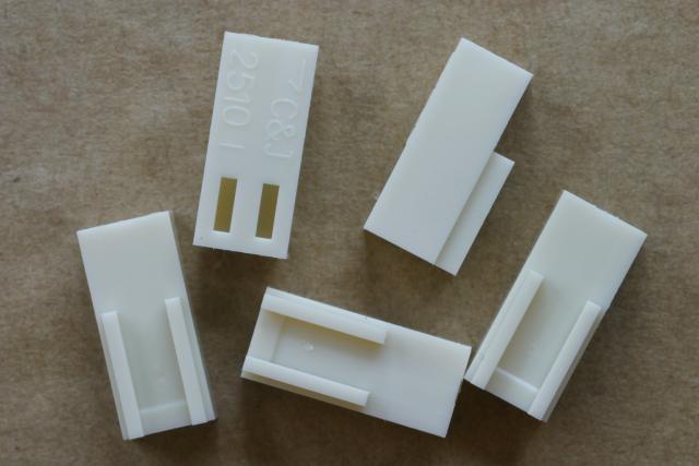
2 way housing, 5 off

3 way housing, 3 off
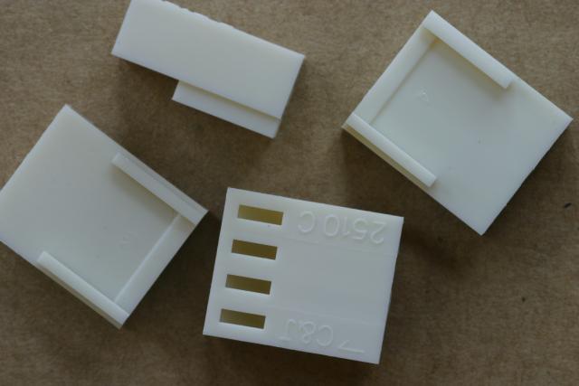
4 way housing, 4 off
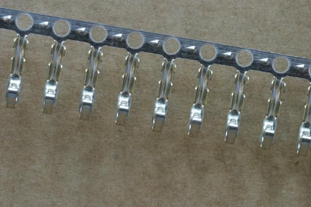
Crimps, 35 off

SD card socket, 1 off

8 pin DIL socket, 1 off
14 pin DIL socket, 1 off
40 pin DIL socket, 1 off (only part of this shown in photo)
DIL means Dual In Line, referring to the type of packaging of the chip that plugs into this socket.
WIRING

IDC sockets, 4 off

IDC ribbon cable, 205mm lengths, 2 off

2 core cable, 1m length, 1 off
The white two core cable is for the hot end heater.

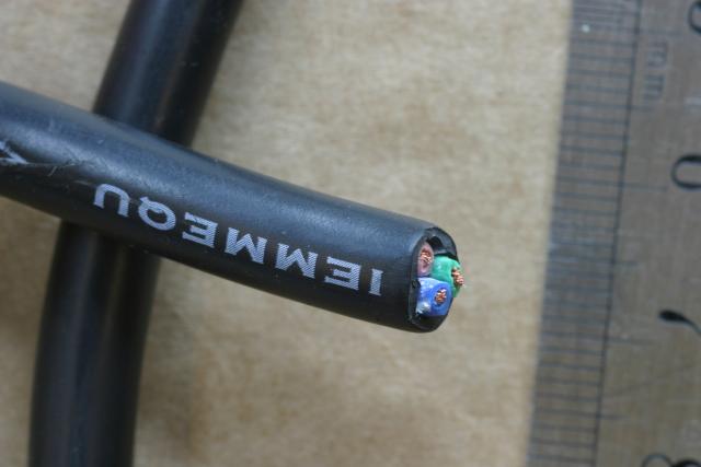
3 core cable, 1m length, 1 off
TODO: As you can see in these 2 photos, I was supplied with TWO lengths. And not only are the two lengths different colours, but the white cable is slightly thicker diameter than the black. Accident? Design?? Who knows?
Further info (Oct 2012): The black three core is to make a mains lead. Attach one end to the power supply and then fit a plug on the other end. Or you may prefer to fit an IEC socket and use an off the shelf lead.
The white 3 core is cut into two parts, one used whole for the PSU to OMC connection, the other part stripped out for the heated bed connections.
The white 2.5mm 3 core cable will need to be cut up into power and heated bed sections, some of which need separating.
Reserved for hitemp and silicone hb term
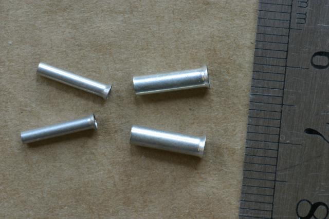
Small ferrule, 2 off
Medium ferrule, 2 off

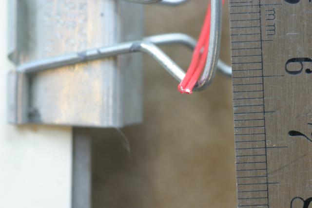
Thermistor, 1 off
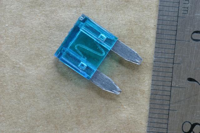
Blade fuse, 1 off
BOM says 2 off, needs updating.

Ceramic fuse, 1 off
Legend on the end cap is: F 16A H250V
Reserved for hitemp (4 items)
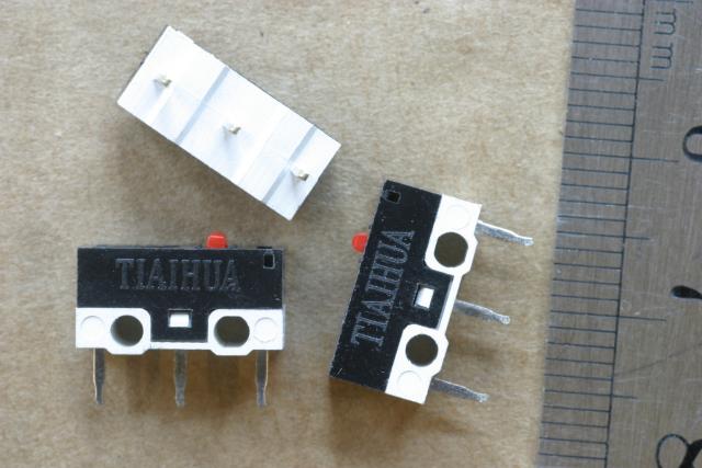
eES micro switches, 3 off

Jumpers
QUANTITY UNKNOWN?

TODO: WHAT'S THIS???

TODO: WHAT'S THIS???
TODO: WHAT'S THIS???
I'm not sure which item this is in the BOM, but elsewhere it has been described as the thinner of the red silicone pairs and is for the heated bed thermistor run via the underside of the heated bed PCB element. It is chosen for its higher temperature range to avoid melting and high temperature perishing.

TODO: WHAT'S THIS???
I'm not sure which item this is in the BOM, but elsewhere it has been described as the thicker of the red silicone pairs and is for a
short run from the heater resistor to the 2 core mains cable. It is chosen for its higher temperature range to avoid melting and high temperature perishing.

TODO: WHAT'S THIS???

Inline fuseholder for ceramic fuse, 1 off
If you have everything identified, you're ready to build it... go to http://tvrrug.org.uk/E-Module-Build-OMC-v1.2 for step by step instructions on doing that.