Electronic Wiring V1.2
 |
Note: ** UNDER CONSTRUCTION - N.B.PICS ARE FROM V1.0 which had different coloured wiring.** Mounting your TVRR Electronics is left to the individual builder. These notes are a guide to wiring your Printer Electronic parts, noting connections and suggestions for avoiding interference etc. These pics show one builders method, another can be seen here The modules are described on the TVRR E-Modules page | |
| Before you start check this visual guide to Wires & Cables and this one to Heat Shrinks |
|
Wiring overview
There is a detailed wiring diagram showing all of the electrical connections you need to make. Refer to that for details such as the order of the stepper-motor wires, and the orientation of the ribbon cables.
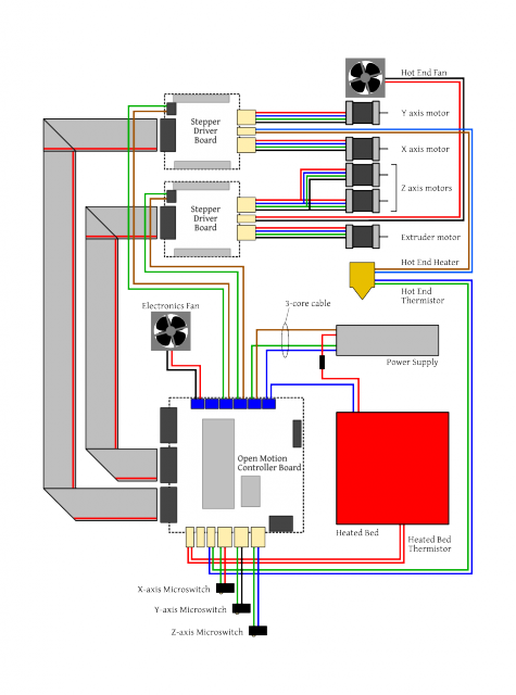
N.B. the schematic layout is from OMC-v1.0 but the markings are correct for OMC-v1.2
 Connecting the OMC to a PC using an FTDI cable. Note. Round 3 FTDI cables may not have the spare pin on the connector, but the sequence of coloured wires is the same.
PSU, OMC 2 x Driver Boards |
|
|---|---|
PSU – |
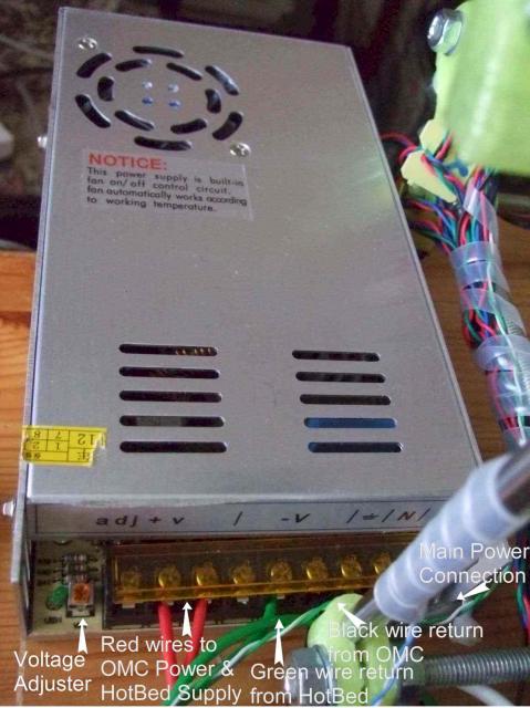
– Michel has designed a cover for the 'live' parts that incorporates an IEC socket and switch. Here we see the standard hinged honey coloured cover. Note: Mains Voltage is fed into the PSU, after this all Voltage is 12V or less although current can be up to 30Amps Tin with solder all the wires to be connected to the PSU terminals to help prevent stray strands of wire causing shorts
|
|
PSU – |
– The PSU and Controller housings are mounted onto a base board. This reduces transfer of vibrations from the Printer |

|
Casing the Electronics – |
– An 80mm fan is used to cool the electronics, this case made of reused aluminium |
|
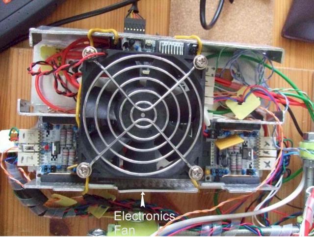
Mounting the Electronics – |
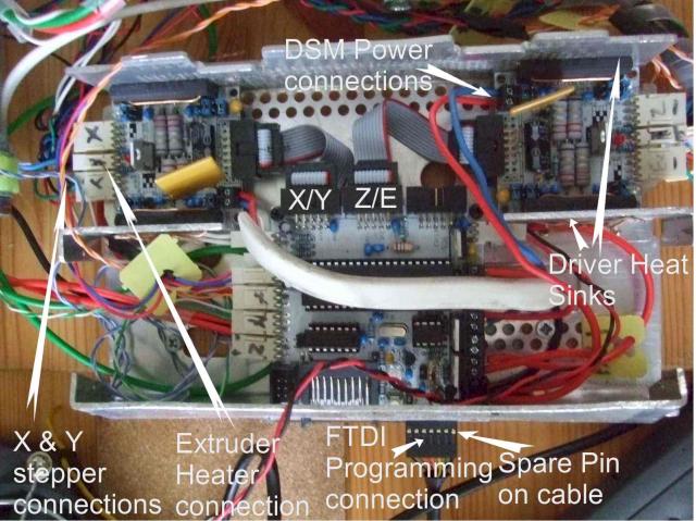
– With the fan removed we can see the layout of the OMC and two driver boards This photo gives a good view of the IDC flat ribbon cables and the orientation of the connectors with a red stripe down one side. You should also refer to the photo to note how to connect the FTDI cable, exposed pin side to the top and a spare socket on the connector is set to the right. A blanking piece could be inserted into the spare pin if wished. |
|
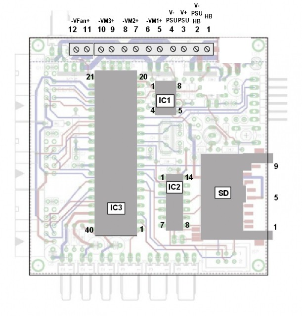
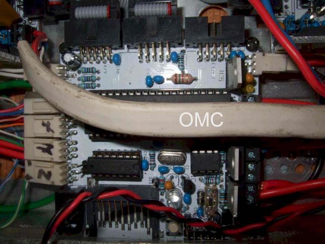
OMC board – |
– Access to the Programming connector, SD Card and Reset button are through a side access panel. The OMC board is supported on two plastic standoffs at the rear and to the case at the front. It is good to be able to view the LED indicators mounted on the OMC board Access to the large chip may be needed in the future to allow for loading new Firmware. The connectors on the left of this photo are from the end-stop microswitches. The other end of these 2 wires are soldered to the N/O pin set on the microswitches. Note: It is likely that end-stop switches will be changed to use the N/C pins in the future, to reduce the chance of them picking up interference, but this will need to be accommodated in the Firmware on the OMC |
|
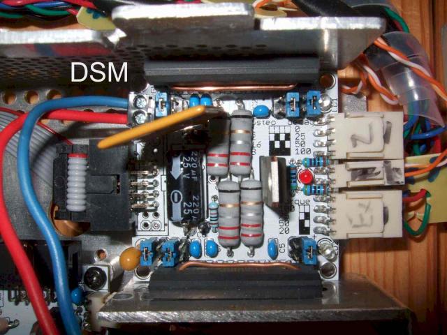
Driver Modules – |
– The 2 driver chips on each board are attached to the casing to allow heat to be disappaited Add jumpers to the headers as shown in the picture, NB The two mirrored header are opposite ways around. |
|
Wiring to the OMC terminals – |
– Here we see the wiring to the screw terminals on one edge of the board. On the right is the connector for the electronics cooling fan that is poowerd whenever the OMC is on. Note that the wires to the screw terminals were tinned in a previous step |
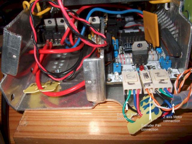
Connections to Driver Modules – |
– Here we see the Extruder Stepper and Z Axis Stepper with the Extruder Cooling Fan connection in the centre. The connections on the stepper shell, when viewed as here from the rear and with the key slot to the top, are coloured Black, Green, Blue, Red, from left to right |
|
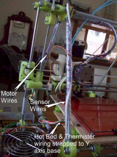
Running the Wires – |
– The Hot End thermister and Heater wires are run up the front A frame and the Motor wires up the rear frame to reduce interference. Helpful hint. Buy a pack of 100 cable ties and use them liberally! |
|
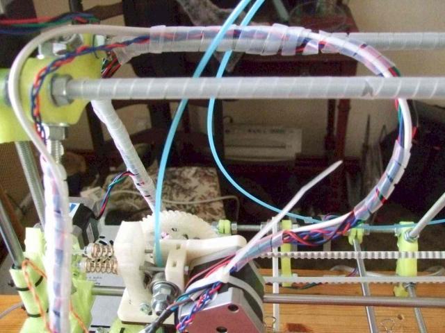
Allowing for the Moving Axes |
Wrap the wiring to avoid rubbing, catching or stretching of wires |
|
Wiring to the Hot End and Bed |
The heating resistor wires are stiff and inflexible so running these avoiding any of the frame can be a be tricky The wiring to Hot Bed is attached to the Y axis base board with a cable clamp. The HB thermister goes to a hole in the centre of the HB and should be held 1mm above the bed surface so that if touches the glass printing surface. It is held in place with Kapton tape or Sugru 6 though holes are located on the HB PCB between the wiring points for optional surface mount LEDs and resistor. (How to Mount LED's) You need only mount 1 LED to get an indication when the HB is powered. If one is used then it must be polarised correctly to match the +/- power connections. An alternative is to mount 2 LEDs in opposite polarisation that so that one will be lit irrespective of the way the power wiring is orientated Note: check the lay of the cables over the full movement of all axes and the full printing envelope |

|
http://tvrrug.org.uk/image/tid/7
Michel has a design he call MetaCube - here is a pic of it
