Second part of frame - Round 2
Pics from Malcolm test build of R2 design
Pictures hosted courtesy of Flickr.com
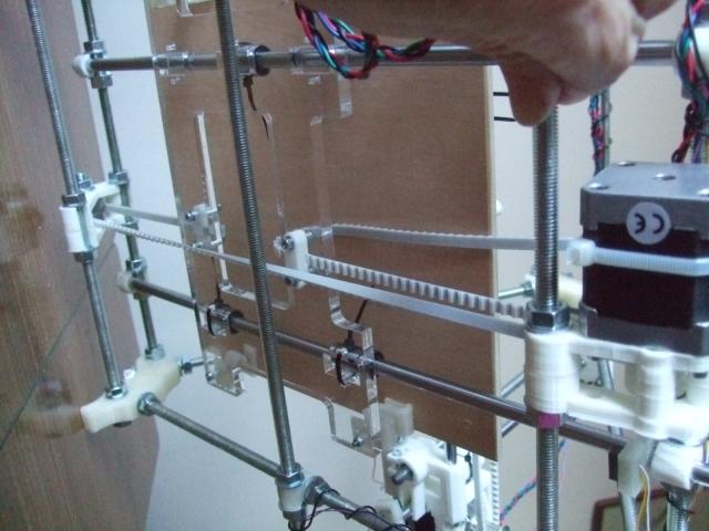
NOTE: the above picture shows the belt cut and joined. THERE IS NO NEED TO DO THIS! Just twist the belt 180 degrees. The belt attaches to the bottom side of the acrylic bed at the motor end, with the smooth side against the acrylic. The teeth engage with the motor pulley. With a twist in the belt between the motor pulley and idler, the back of the belt should go over the idler and attach to the top side of the acrylic bed, to line up.
Shows the belt path correctly, though the belt has been cut and joined, rather than a twist put in it.
Pics from MIkeTheBee
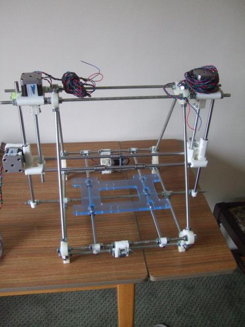
This is a general view of the frame (NB this pic shows the perspex bed mounted above the Y-rods, it can be mounted this way, but we expect most builders will mount the perspex below the Y-rods for maximum Z travel, as show in the pics below)
Perspex bed mounted underneath Y-Rods, orientated correctly so the cut out in the acrylic bed fits around the motor. The Y-axis motor is at the bottom of the picture, the Y-idler is at the top. Note the mounting of the X-Z-threaded rod (the rod below the acrylic bed) is below the triangle frame units. The Y-belt has the clamp on the underside of the perspex bed, the clamp indents engage with the teeth on the belt and trap it between the clamp and the perspex.
The belt is tensioned using the new Y-idler adjuster bolts
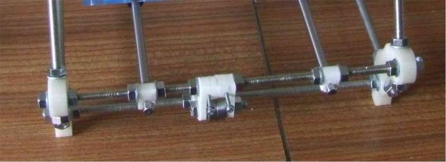
The new rod clamps joining the Y-frame and X/Z lower threaded bar. I have used 4off M8 Nuts (2 each on both threaded rods), this is not correct for the TVRR2 kit which only needs the supplied 2off M8 nuts. We need to confirm which axis the 'hook' side of the rod-clamp goes onto, I guess it should be the Y frame bottom and the nuts go on the X-Threaded-Rod
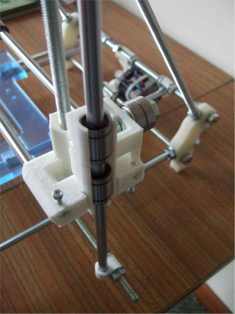
Z-axis linear bearings before strapping with cable ties. It may be necessary to bind the bearing around with kapton tape (1 layer=0.2mm) with around 5 layers to provide a firm hold of the bearing within the X-Idler. This pic also show the mounting of the double bearing idler that supersedes the single bearing version used in Round 1
A view of the new Z-Isolator. This clamps to the Z nut and sits under the X-Ends. The "fingers" should be "eased" with a file to the size where they move smoothly up & down with minimum horizontal slack
Go to the third part of the frame build.


