Frame Build Round2
The frame is more or less a standard Prusa frame as was the Round 1 build.
However, we have some modifications from that design. In summary these are:
- Bearings are doubled up on Y and X idlers.
- The Bed is now lasercut perspex instead of plywood, this removes the need for printed linear bearing holders (LM8UU), and allows for 3 or 4 linear bearing to be used.
- Y-Axis motor and idler mounts are significantly different design.
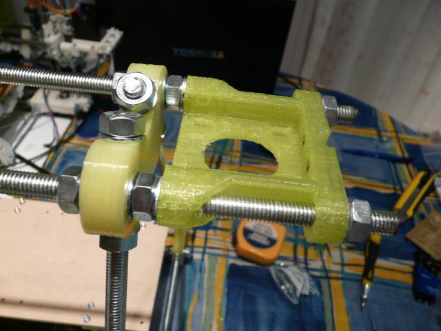
- X-axis mounting at Z.: There is now a thing called a "Zizzilator" that clamps onto the Z M8 lift nut instead of it being directly on the X-Z printed parts.
- We are building slightly wider than normal, in order to fit the heated bed design in: The horizontal distance between the vertices across the X-axis should be 250 mm.
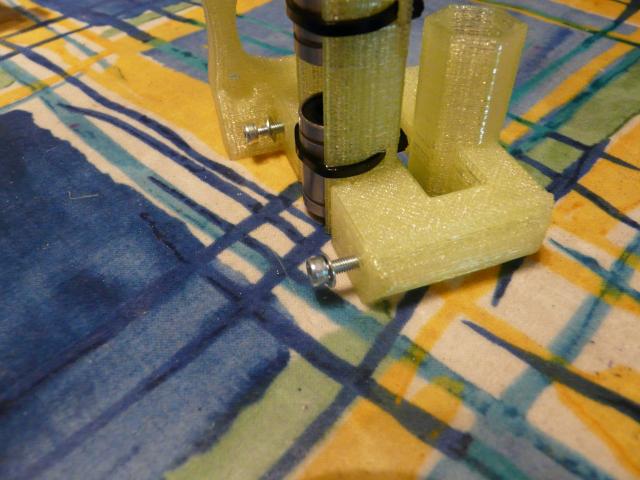
- The front threaded rods have a slightly different design and order of parts: nut — washer — y bracket — washer — washer — bearing guide — washer — nut. The Rod Clamps are now designed to clip onto the threaded rod, this avoids having to undo the M8 Nuts to fit or remove the smooth rods on the Y-Axis.
Basic Build Steps for the TVRR 2
Check all holes for sizing, clean and "ease" as needed. Evaluate your linear bearings and smooth rods to create the best match of each.
Build Triangular Frames - check for matched sizing

Link to original RepRap guide that are the source for some of these pics
TVRR 2 has the post build clip newly-clamp as an alternative to the standard one shown here.
Build horizontal threaded rods sets with nuts, washers in place

Join End Frames with Horizontal rods, set in measured positions, check squareness in X/Y&Z
Add Z motor mounts

Add Lower X Threaded Rod 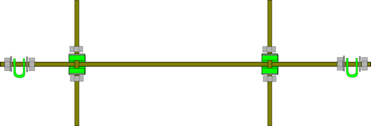
Assemble Y-Axis, add linear bearings to Y smooth rods, attach them to the Perspex lower bed. The bed will be underneath the rods when mounted Add the belt clamps to the perpspex bed, the front to the underside and the rear to the top side. Add end-stop micro-switch mount.

Mount Y Belt and add Y-Motor and Ider Mounts to check length of belt needed
Assemble the X-Axis - adding linear bearing and end-stop micro-switch mount to motor end
YouTube Video of X-Axis Assembly
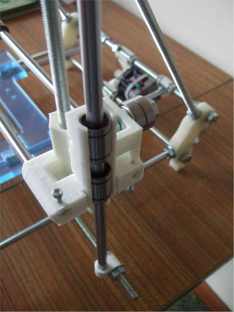
Assemble the Z-axis, mounting the Clamps at the top and the Zizzisolators at the bottom, with captive M8 nut
-
Fit the Z axis threaded smooth rods, aligning them vertically
- Z Motor Mount x 1
- M3 nut x 2
- M8 washer x 4
- M8 nut x 2
- Rod clamp x 1
- M3x20 bolt x 2
- M3 washer x 2
- 350mm Smooth Bar x 1
- Motor x 1
- Plastic tubing x 1
- Coupling x 1
- M3 nuts x 4
- M3x20 bolts x 4
- M3 washer x 4
- Z leadscrew (210mm M8 studding) x 1
Z Axis
Z Motor Mounts x 2
Trap the M3 nuts in the slots. Secure the Z motor mount to the frame. The flat side of the motor mount goes at the bottom, and the side with the captured nuts goes on the outside.

Z Smooth Bar x 2
You can install the Z smooth bar at this point, although it will need to be removed to install the X axis.
Insert the smooth bar into the bar clamp at the bottom of the frame, and use the M3x20 bolts and rod clamp to secure it at the top to the Z Motor Mount. Do not fully tighten yet.
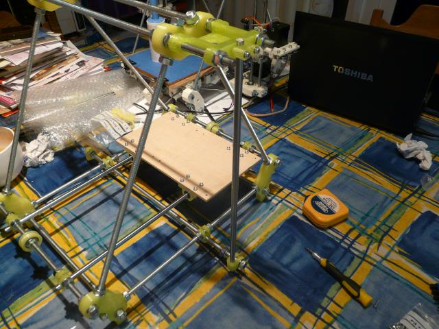
Z Motors and Leadscrews x 2
Put the tubing on the motor shaft and sit the motor on the Z motor mount.Capture the nuts in the half of the coupling with nut recesses.

Use the M3x20 bolts with a washer each to loosely join the two halves of the coupling together. Slide the coupling over the tubing on the motor shaft until the bottom of the shaft is at the middle of the coupling. Insert one end of the leadscrew into the other end of the coupling, until it meets the bottom of the motor shaft. Tighten the M3x20 bolts evenly, keeping the leadscrew straight and square.
-
SUMMARY: Build X Axis, fit the X-Axis onto the Z-Axis and install the X carriage on the X-axis
-
N.B. Add the end-stop mico-switch holder before locking Z-Smooth Rod into lower bar clamp
X Axis
- X Motor End x 1
- X Idler End x 1
- M3 nut x 2
- M3x10 bolt x 2
- LM8UU linear bearings x 4
- Cable ties x 4
- M8 nut x 1
- M3x20 bolt x 2
- M3 washers x 4
- M3 nyloc x 2
Use an 8mm drill bit to remove the support material covering the lead nut hole from the x ends. Note that the nut is help in the Zizzisolator for Round2 design.
Capture the M3 nuts in the X Motor End slots. Tip: Hold the X smooth bar vertically and place the nut on the end in the centre. Push the X Motor End down onto the smooth bar until the nut reaches the nut recess. Use an M3x10 bolt with a washer to draw the nut into the recess.
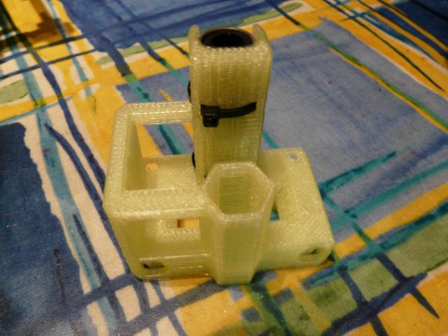
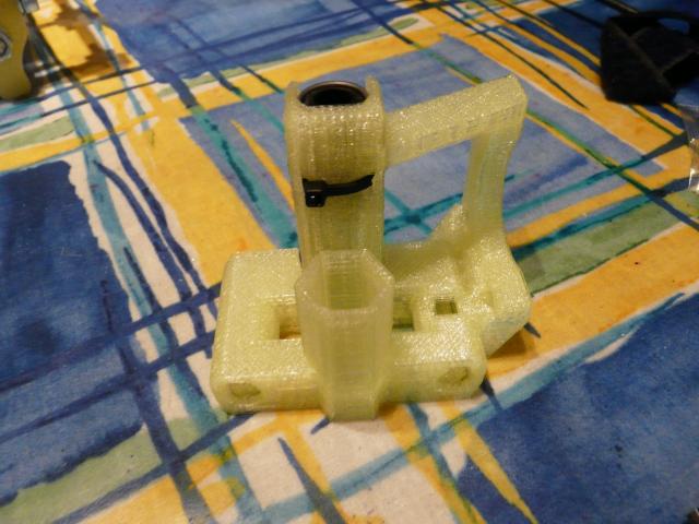
Press the linear bearings into the X ends, making sure they are straight and sit within the notches. Cable tie them in position, trimming off the ends of the ties.


Screw the M3x10 bolts into the X Motor End just until the engage with the nut. (The washers are unnecessary and may cause a rattle when printing, so it is best to omit these despite the picture).
Slide the left Z smooth bar up and out of the bottom clamp, position the X motor end underneath and slide the Z smooth bar down through the linear bearings and back into the clamp. Slide the X motor end up the smooth bar and onto the leadscrew. Screw the M8 nut onto the leadscrew beneath the X motor end and let the X motor end sit on the nut.
Repeat on the right hand side with the X idler end.
Approximately square the Z smooth bars and level the X ends by eye. Insert the X smooth bars through the holes in the X idler end and into the slots in the X motor end. Use the M3x20 bolts to hold the rods in place. Do not tighten the nylocs yet as the X carriage still needs to be added.
Troubleshooting if the X smooth bars are too long:
- Is the distance between the washers on the inside of the vertices 250mm?
- Is the distance between the outsides of the z smooth rods 414mm (give or take a millimetre)? If not, do you have washer - nut - washer between the vertices and the z motor mounts?
- Have you pushed the captured nuts into the x motor end as far as they can go and can the M3x10 bolts be unscrewed any more?
- Are the linear bearings fully inserted into the x ends?
- How much off-square are your z smooth rods? If they are even only a little bit wonky, this can make the x smooth rods appear the wrong size
If fixing these does not solve your problem, add extra washers between the vertices and z motor mounts to space the Z smooth bars further apart, if the bottom threaded rod is long enough. Let us know where you get to, if you are still having problems we can arrange to meet up.
X Idler Bearing
- M8x25 bolt x 1
- M8 washer x 4
- M8 nut x 1
- Bearing x 2
Attach the bearing guide to the X idler end. The order is:
- M8x25 bolt
- M8 washer
- Bearing
- Bearing
- M8 washer x 2
- X idler end
- M8 washer
- M8 nut
Install Carriage, Belt and Bed. Basically follow Round 1 Instructions
Build and Mount the Wade Extruder. N.B. Round2 uses a NyLok nut on Hobbed Bolt
Wire Electronics to End-Stops, Hot Bed, HB Thermistor, Wade Heater, Hot End Thermistor, and Motors. Do NOT try to run the electronics until the Firmware has been loaded.
TO BE CONTINUED
Pictures of the correct assembly are also here on Flickr
Motor end belt clamp
Go to the second part of the frame build.


